Part 4 – drilling the PC board and assembling
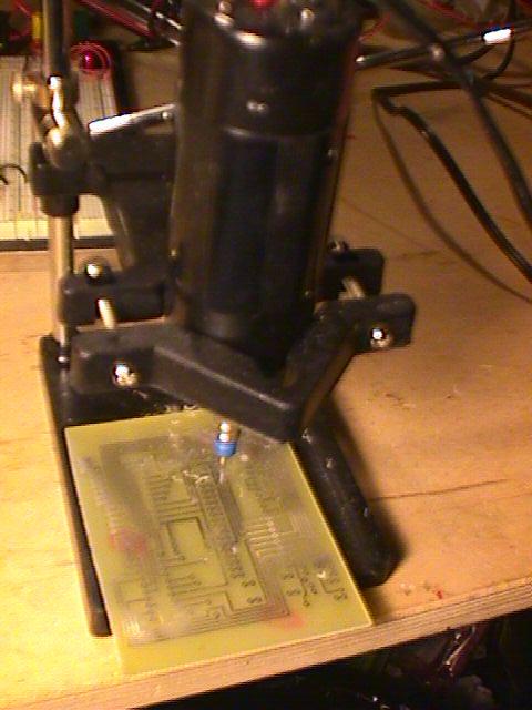
Drilling the board is kind of tricky. I bought a really cheap drill press called an Octopus from Jameco. Here is a picture with a board ready to drill with the drill press:

The drill bit size is key to a successful project. I use #69 .0292 bits that I got from Drill Bit City, but I later found that #66 drills worked better. Here is a picture of the drilled PC board. Another possibility for a circuit board is to use something like Radio Shack #276-158b and do point to point soldering. This worked out for me quite nicely on my PV controller on SolarPower.org. Much of the circuit is similar, since I use an 8048 as well, and it fit just fine on the Radio Shack board. The circuit has run for over a year without any problems.
For the case, I used Radio Shack part #270-1806. I power the unit with 4 AA batteries with a 1N4148 diode in series that drops the voltage down close enough to 5 volts to work. This is much more efficeint than running the circuit through a regulator like the 7805. Right-click and save. Here is a hex dump view of the program. You could also enter this in byte for byte on a 2816 EEPROM using jumper wires and a breadboard, since the program is fairly small. Here are plans for a EEPROM programmer that works via a PC printer port. Oh, one other tangential factoid here. Don’t buy bulbs for your EPROM eraser from the eraser manufacturer or distributor. I can buy G4T5 bulbs from topbulb.com for $7.50, but they cost over $34 from Jameco. Look on the part number on the bulb, not the eraser.
Now for some pictures of the remaining assembly:
Bottom of the PC Board with components soldered on
Closeup of the transistors I really like the metal canned 2n2222As, don’t you? The straight-through LED is lit. I ended up wiring the LEDs separately, but there is room on the board to hold them if needed
Closeup of the 8048 CPU and 2716 memory. I didn’t end up using these exact chips, although they work fine. For this particular circuit, since it was battery powered, I used an Atmel AT28C16, a 74HC373AP, and an 8048AH. I got the power draw down to 48 milliamps, and that is with the power LED on. The 80c39 would be another fine choice, and would probably reduce power consumption even further, but you might need to adjust the circuit a wee bit to deal with the CMOS characteristics. Jameco has a bunch of 80C39s (thousands). You can also find 8048 chips in old XT keyboards
Ready to put the lid on Notice how I used Cat5 couplers heat glued in notches I cut out of the side of the case. I also stuck a 1000uF capacitor between ground and the switched side of the power.
I’ve got a classic heat glue gun. You can’t get this model any more. For me, heat glueing should involve your thumb. 🙂
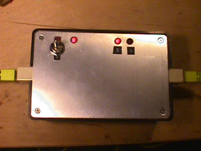
And here is the completed Cat5 Cable tester:
Notice that we have a straight-through cable plugged in and the “S” LED is lit.
There are five parts to this article:
Build Your Own Cat5 Cable Tester – Introduction
Part 1 – How to wire Cat5 cables, and how they work


