Like anything else, keylogging can be used for good, or for evil. Here is a list of related links, including both hardware and software keyloggers. (Yow!) Regardless of the privacy issues, there are also security issues as well.
Some trojans will install keylogger software as part of their kit. There are also keyloggers geared for employers to spy on employees, or for parents to spy on their children, with information being sent to a central location (such as a syslog server/software) or hardware device. For software keyloggers, there are detection routines used by network monitoring tools and software that will catch them. For hardware keyloggers, the only way to detect them is through physical inspection.
Since hardware keyloggers are physical devices (or, as we shall see, a few well placed wires to monitor and capture network data), physical security can prevent hardware keylogging. It is also possible to confuse hardware keyloggers by sending tons of bogus data in between valid keystrokes. We wondered how, exactly, the hardware keyloggers worked, so we did a little investigation.
We found a lot of good technical details about keyboard communications here. We also used our trusty 80×86 IBM PC and Compatible Computers: Assembly Language, Design, and Interfacing Volume I and II by Muhammad Ali Mazidi and Janice Gillispie Mazidi book for this article. If you want to understand PC hardware, this is the best book we have ever seen on the subject.
The PC keyboard uses a microcontroller to send scan codes to the motherboard. The original XT used an 8048 for this purpose, but modern keyboards use later variants. (We used an 8048 in our article Build Your Own Cat5 Cable Tester.) The scan codes are sent in serial. There are 11 bits total. One start bit, 8 data bits, an odd parity bit, and a stop bit. The data line transmits the bits, and the clock line signifies the bits are valid when low.
The clock line is pin 1 on a 5-pin (AT/XT) keyboard plug, and pin 5 on a 6-pin (PS/2) keyboard plug. The data line is on pin 2 of the 5-pin plug and pin 1 of the 6-pin plug. Ground is on pin 4 of the 5-pin, and pin 3 of the 6-pin plug. For more info on the physical connectors, check out these diagrams. There is another microcontroller on the PC motherboard that receives this serial data and interacts with the CPU. The microcontroller on the motherboard signals the CPU via interrupt 1. Verify this:
u-1@srv-1 proc $ cat /proc/interrupts | grep keyboard 1: 47226 XT-PIC keyboard u-1@srv-1 proc $ |
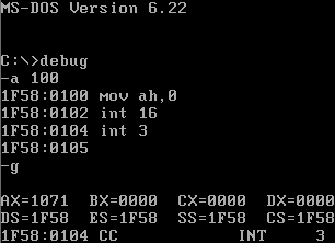
The data from the keyboard is stored in the keyboard buffer. When the CPU gets the interrupt, it looks in the keyboard buffer area to see the data. Do you have an old DOS 6.22 floppy hanging around with debug on it? Well, go dig one up. Here is how we can use the BIOS routine INT 16H to read the character in the keyboard buffer:
If we press a q after the g, the ASCII code shows up as 71 in AL (the right half of AX). What we need, though, is to decode the stream of data from the keyboard to the PC before it gets to the microcontroller on the motherboard. One possibility is to do this entirely with hardware. We tapped in to the data, clock and ground lines by stripping away the insulation from a keyboard extender, and soldering the wires to a piece of perfboard.
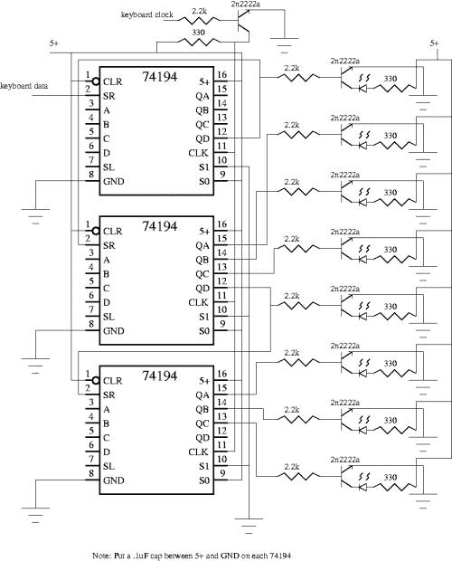
We just so happen to have exactly three 74194 four-bit shift registers in our lab, so that is what we used for our hardware decode solution. We hooked the data line up to the SR line on the 74194. The 74194 shifts when the clock goes from low to high. When you set S0=high and S1=low, the data on the SR line gets shifted right. Now, there are eleven clock transitions for each part of a scan code. For the alphanumeric scancodes there is only one code which is transmitted at make, and two codes in sequence at break. Make is when you first press the key, and break is when you release the key.
The last code of the break sequence is the same as the make code, so the last sequence of 11 clock signals is the valid decode of the keyboard. We ran the clock into a 2n2222a NPN transistor that acts both as an inverter, and as a buffer for the three pure-blooded TTL loads. At the first transition, the data line is the stop bit. This immediately gets shifted right, so bit 0 never has valid data. Another eight shifts transmit the data, then we shift for the parity and stop bit. This means that bits 3-10 are the decoded “make” part of the scan code for the key.
Here is the schematic (click for larger one)
Here is a fig file of the schematic
For more information on the program used to generate the schematic, click here.
Here is the breadboarded circuit decoding q
Notice how we tapped in to the keyboard on the left. The scan code for q is 15, which you can see in binary on the display.
Here is a closup of the transistors
Well, that was a lot of fun. An easier way to decode this would be to use software and snag the data from a couple lines on the parallel port. First, you need to find out what i/o port your parallel port is using:
srv-1 keylogger # cat /proc/ioports 0378-037a : parport0 |
Here is a picture of where we soldered the three wires to the printer port.
[Please read our terms of use. Don’t run this program or attach wires to your PC unless it is a test system you can afford to crash.] We hooked the clock line up to pin 10 and the data line up to pin 12. Pin 10 is the Ack signal on the printer, and it is an input line (from the PC perspective). Pin 12 is the out of paper signal, and is an input line as well. Pins 18-25 are attached to ground. This is well documented in the Mazidi book. For more info, and the plans to build an opto-isolated interface, see this article. Here is the program we wrote up that will decode the data from the keyboard via the printer port:
#include <stdio.h>
#include <stdlib.h>
#include <unistd.h>
#include <asm/io.h>
int main(){
ioperm(0x379,1,1);
int i;
char scanres, curbit, keytxt;
scanres=0x0;
curbit=0x1;
ioperm(0x379,1,1);
/* wait for clock to go low, high, and low again */
while((inb(0x379) & 0x40) != 0x00){}
while((inb(0x379) & 0x40) != 0x40){}
while((inb(0x379) & 0x40) != 0x00){}
/* ok, ready for 8 bits. Rotate curbit w/ data */
for (i=0;i<=7;i++){
if((inb(0x379) & 0x20) == 0x20)
scanres=scanres + curbit;
/* wait for high, low */
while((inb(0x379) & 0x40) != 0x40){}
while((inb(0x379) & 0x40) != 0x00){}
curbit= curbit << 1;
}
switch (scanres){
case 0x16: printf("1");break;
case 0x1e: printf("2");break;
case 0x26: printf("3");break;
case 0x25: printf("4");break;
case 0x2e: printf("5");break;
case 0x36: printf("6");break;
case 0x3d: printf("7");break;
case 0x3e: printf("8");break;
case 0x46: printf("9");break;
case 0x45: printf("0");break;
case 0x15: printf("Q");break;
case 0x1d: printf("W");break;
case 0x24: printf("E");break;
case 0x2d: printf("R");break;
case 0x2c: printf("T");break;
case 0x35: printf("Y");break;
case 0x3c: printf("U");break;
case 0x43: printf("I");break;
case 0x44: printf("O");break;
case 0x4d: printf("P");break;
case 0x1c: printf("A");break;
case 0x1b: printf("S");break;
case 0x23: printf("D");break;
case 0x2b: printf("F");break;
case 0x34: printf("G");break;
case 0x33: printf("H");break;
case 0x3b: printf("J");break;
case 0x42: printf("K");break;
case 0x4b: printf("L");break;
case 0x1a: printf("Z");break;
case 0x22: printf("X");break;
case 0x21: printf("C");break;
case 0x2a: printf("V");break;
case 0x32: printf("B");break;
case 0x31: printf("N");break;
case 0x3a: printf("M");break;
case 0x29: printf(" ");break;
}
printf ("\n");
}
|
You can get more info on the ioperm command here. This is all GNU/Linux specific. Once we pass the first clock transition, we calculate the scan result (scanres) by adding the value of the current bit location (curbit) if true. When we start, if the data line is high for bit 0, curbit=1, which we then add to scanres.
At each iteration we use << 1 to rotate curbit left by one. So, on the second bit (iteration), curbit is 2, and so on, until on the eighth iteration the value of curbit is 128 (or 80H). To compile and run the above program:
srv-1 keylogger # gcc logkey.c -o logkey srv-1 keylogger # ./logkey Q srv-1 keylogger # |
In the above example, a Q is displayed after the “q” key is pushed. This program only decodes one key at a time. It also does not distinguish between upper and lower case, and only decodes alphanumeric keys. Here is the source code for the above program in file format. Enjoy.


